Difference between revisions of "NG 900/9-3 Replacement of Sensonic Clutch Actuator Without Master Cylinder"
| Line 5: | Line 5: | ||
1. Turn the ignition switch to the OFF position and remove the battery. | 1. Turn the ignition switch to the OFF position and remove the battery. | ||
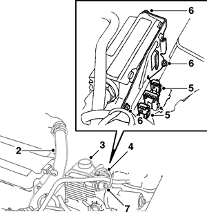
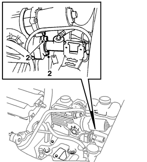
| − | [[file: | + | [[file:Sensonic_Actuator_01.gif|thumbnail|none|Charge Pipe, Power Steering Reservoir, Clutch Actuator]] |
2. Remove the pressure pipe between the charge air cooler and throttle body and seal the hose to prevent dirt from entering it. | 2. Remove the pressure pipe between the charge air cooler and throttle body and seal the hose to prevent dirt from entering it. | ||
| Line 20: | Line 20: | ||
8. Unscrew the bolts securing the battery tray. | 8. Unscrew the bolts securing the battery tray. | ||
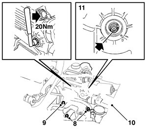
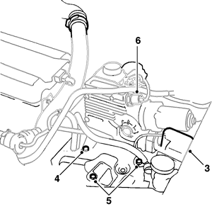
| − | [[file: | + | [[file:Sensonic_Actuator_02.gif|thumbnail|none|Battery Tray and Clutch Actuator]] |
9. Remove the remaining bolts securing the CA unit. | 9. Remove the remaining bolts securing the CA unit. | ||
| Line 29: | Line 29: | ||
12. Remove the two screws securing the master cylinder. | 12. Remove the two screws securing the master cylinder. | ||
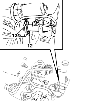
| − | [[file: | + | [[file:Sensonic_Actuator_03.gif|thumbnail|none|Master Cylinder and Clutch Actuator]] |
13. Remove the clip securing the pressure pipe to the CA unit's holder. | 13. Remove the clip securing the pressure pipe to the CA unit's holder. | ||
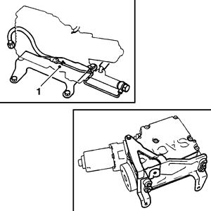
| − | [[file: | + | [[file:Sensonic_Actuator_04.gif|thumbnail|none|Clutch Actuator]] |
14. Lift out the CA unit. | 14. Lift out the CA unit. | ||
| Line 39: | Line 39: | ||
1. Position the clutch actuator unit and fit the clip securing the pressure pipe to the CA unit's holder. | 1. Position the clutch actuator unit and fit the clip securing the pressure pipe to the CA unit's holder. | ||
| − | [[file: | + | [[file:Sensonic_Actuator_05.gif|thumbnail|none|Clutch Actuator]] |
2. Replace the two screws securing the master cylinder to the CA unit. | 2. Replace the two screws securing the master cylinder to the CA unit. | ||
| − | [[file: | + | [[file:Sensonic_Actuator_06.gif|thumbnail|none|Replace Screws Securing Master Cylinder to Clutch Actuator]] |
3. Fit the maxifuse fuse box back in place. | 3. Fit the maxifuse fuse box back in place. | ||
| − | [[file: | + | [[file:Sensonic_Actuator_07.gif|thumbnail|none|Rebolt Clutch Actuator and Battery Tray]] |
4. Tighten the screws securing the clutch actuator unit. | 4. Tighten the screws securing the clutch actuator unit. | ||
| Line 54: | Line 54: | ||
7. Fit the wiring harness in place, press the connectors into the holder and tighten the holder's three retaining screws. | 7. Fit the wiring harness in place, press the connectors into the holder and tighten the holder's three retaining screws. | ||
| − | [[file: | + | [[file:Sensonic_Actuator_08.gif|thumbnail|none|Reassembly]] |
8. Plug in the three sensor connectors. | 8. Plug in the three sensor connectors. | ||
Revision as of 00:40, 15 February 2010
Notes
Important: After work has been carried out on the clutch actuator unit, hydraulic system, clutch, etc., the clutch may exhibit a tendency to snatch. This should normally disappear after adaptation of the slip point.
Removal
1. Turn the ignition switch to the OFF position and remove the battery.
2. Remove the pressure pipe between the charge air cooler and throttle body and seal the hose to prevent dirt from entering it.
3. Lift up the power steering fluid reservoir and turn it to one side.
4. Unplug the three sensor connectors.
5. Press the connectors out of the holder.
6. Remove the three bolts and lift out the holder.
7. Unplug the CA unit's connector.
8. Unscrew the bolts securing the battery tray.
9. Remove the remaining bolts securing the CA unit.
10. Undo the maxifuse fuse box and move it aside.
11. Remove the cap on the CA unit and check that the CA unit's worm gear is in the engaged position (position E). If it is not, rotate it to the engaged position using a torque wrench set for 20 Nm.
12. Remove the two screws securing the master cylinder.
13. Remove the clip securing the pressure pipe to the CA unit's holder.
14. Lift out the CA unit.
Replacement
1. Position the clutch actuator unit and fit the clip securing the pressure pipe to the CA unit's holder.
2. Replace the two screws securing the master cylinder to the CA unit.
3. Fit the maxifuse fuse box back in place.
4. Tighten the screws securing the clutch actuator unit.
5. Fit the bolts securing the battery tray.
6. Plug in the CA unit's connector.
7. Fit the wiring harness in place, press the connectors into the holder and tighten the holder's three retaining screws.
8. Plug in the three sensor connectors.
9. Refit the power steering fluid reservoir.
10. Refit the pressure pipe.
11. Put the battery back in place.
12. Drive the car to test and adapt the slip joint.
